LED Resistor Calculator

A current limiting resistor, sometimes called a load resistor, or series resistor, connects in series with a light emitting diode (LED) so that there is a correct forward voltage drop across it. If you are wondering, "What resistor should I use with my LED?", or if you were wondering what resistor you should use with 12 V or 5 V supply, then this article will help.
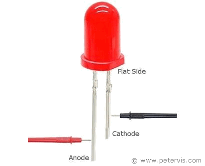
In the diagram above, you can see the pinout of the LED. The cathode is the negative terminal, and this is the flat side of the diode, and the terminal on that side is shorter. Consequently, the anode is positive and it has a longer terminal. If you are always wondering which is negative or positive, then the animation above will help train the brain. Just look at it for a while, and hopefully, it will sink in...
Current Limiting Resistor Calculator - Series

Forward Voltage
The forward voltage drop commonly referred to simply as forward voltage is a specific value for each LED. You can obtain this from the datasheet of your component. However, if you cannot find the specification, then you can always refer to the chart shown below. It shows the forward voltage drop for each commonly available LED by colour. Alternatively, you can also measure it using your digital meter. Almost any cheap meter has this lesser-known capability.
How to Measure Forward Voltage Vf

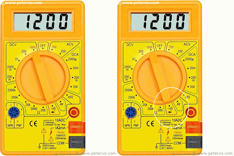
If you have a digital multimeter, then you can also measure the forward voltage drop. Your meter will have a diode symbol on the front dial, so just move the selector switch to that and measure it! Most engineers do not know about this feature, so keep it a secret!

The red probe of the meter connects to the anode, and the black probe connects to the cathode lead, which is the shorter lead. Your digital meter should provide you with a good accurate value that you can use.
Chart by Colour
| LED Colour | Forward Voltage Vf | Forward Current If |
| White | 3.2 V to 3.8 V | 20 mA to 30 mA |
| Warm White | 3.2 V to 3.8 V | 20 mA to 30 mA |
| Blue | 3.2 V to 3.8 V | 20 mA to 30 mA |
| Red | 1.8 V to 2.2 V | 20 mA to 30 mA |
| Green | 3.2 V to 3.8 V | 20 mA to 30 mA |
| Yellow | 1.8 V to 2.2 V | 20 mA to 30 mA |
| Orange | 1.8 V to 2.2 V | 20 mA to 30 mA |
| Pink | 3.2 V to 3.8 V | 20 mA to 30 mA |
| UV | 3.2 V to 3.8 V | 20 mA to 30 mA |
Here is a chart showing the forward voltage by colour for commonly available LEDs on eBay. These are very cheap now and you can get a bag of high brightness light emitting diodes for virtually pennies. All of these are available in 3 mm, 5 mm, and 10 mm sizes. The cathode lead is typically 17 mm long, whilst the anode is 19 mm long.
Due to the non-linear nature of the diode characteristic curve, an LED operates within a very narrow range of forward voltage and forward current parameters. For example, a red LED has a typical forward voltage of 1.8 V and a maximum forward voltage of 2.2 V. It has a typical forward current of 20 mA, and a maximum forward current of 30 mA. Electronic engineers generally use the typical operating parameters.
The great thing about these LEDs is that they all have a typical forward current of around 20 mA, which means that you could apply Ohm's Law to work out the series resistor value.
Choosing the resistor to use with LEDs
| Supply Voltage Vs | Vf = 1.8 V | Vf = 3.2 V |
| 3.3 V | 75 Ω | 5 Ω |
| 5 V | 160 Ω | 90 Ω |
| 9 V | 360 Ω | 290 Ω |
| 12 V | 510 Ω | 440 Ω |
As you can see from the chart above, there are two forward voltages typically used. The red, yellow, and orange LEDs fall into the 1.8 V category, and the white, blue, green, pink, UV, fall into the 3.2 V category. Hence, I have compiled another chart showing the series resistor values required for these two categories of voltage drop. The chart shows the calculated values for when the supply voltage is 3.3 V, 5 V, 9 V, and 12 V. These are the typical voltages used by hobbyists for their projects. Just use the standard resistor values chart to find the nearest highest value available.
Example 1: The blue LED has a typical forward voltage drop of 3.2 V, therefore a 5 Ω resistor is required when using a 3.3 V supply voltage. However, if you are using a 5 V supply voltage, then a 90 Ω resistor is needed. As you can see, the resistor value increases as the supply voltage increases.
Example 2: If you are using a yellow LED, then it has a typical forward voltage of 1.8 V. Hence, resistor values of 75 Ω, 160 Ω, 360 Ω, and 510 Ω, can be used when the supply voltages are 3.3 V, 5 V, 9 V, and 12 V, respectively.
Formula for calculating resistor values

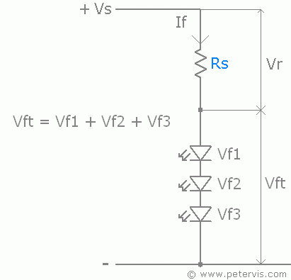
The voltage across the rail Vs is equal to the sum of voltages across the LED and resistor. Given the forward voltage of the diode Vf, the voltage across the resistor is equal to Vs – Vf. Given the forward current, we know that this same current flows through the circuit in the resistor as well. Hence, we have all the information to use Ohm’s Law to calculate the value of the series resistor.
Multiple LED Circuit - Series

Multiple LEDs can connect in series, however the supply voltage limits the number of LEDs you can have. As you can see, the total forward voltage is the sum of all the forward voltages presented by each led. Obviously, the sum forward voltage has to be less than the supply voltage. If you are using a 12 V supply then you could have up to seven LEDs in series.
Multiple LED Circuit - Parallel

The proper way to connect multiple LEDs in parallel is like this, and each LED has its own dedicated current limiting resistor.
In this configuration, you can have many LEDs; however, the limiting factor is the amount of current the power supply can provide. The total current is the sum of all the individual forward currents of each LED.