Germanium Diode Test
A germanium diode is a vital component in the construction of crystal radios, and the quality of the diode will determine how well the radio operates. If you are new to building crystal radios, then the first thing to learn is how to distinguish between germanium and silicon types of diodes. It is certainly worth knowing how to determine this difference because shops can make a mistake and send you the wrong component, or perhaps you may have a bag of mixed diodes and do not know which might be the best one to use. One quick method of making this determination is by a parameter known as threshold voltage. I will explain what this parameter means in more detail later in this page; however, a quick tip is that you can measure it using the diode test function of your meter.
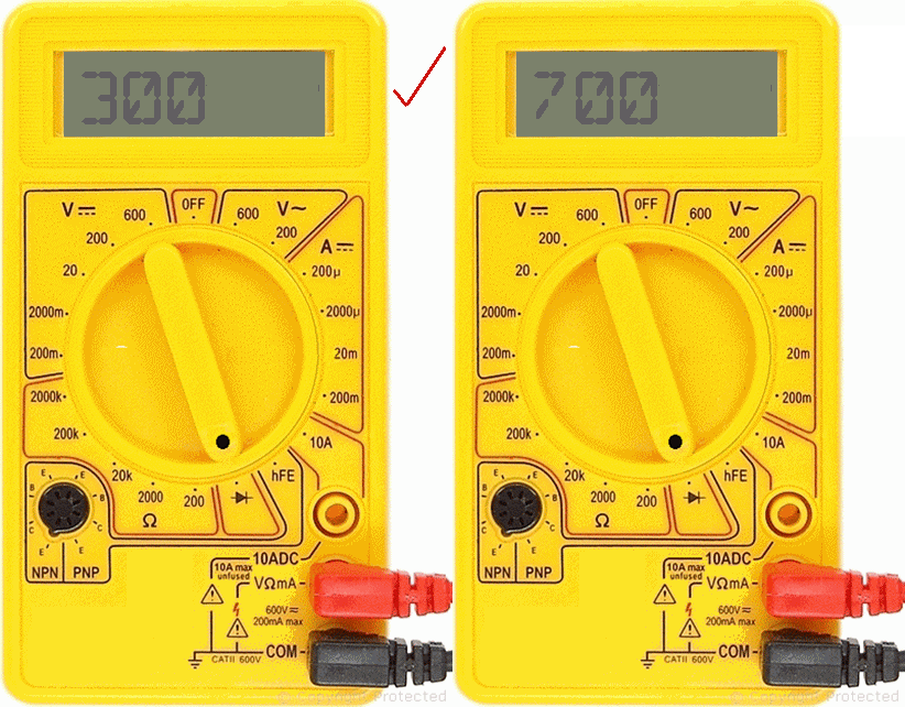
The general rule-of-thumb is that silicon diodes have a threshold voltage of approximately 0.7 V or more, whilst the germanium diodes have approximately 0.3 V or less. Exceptions to this rule are a special group of silicon Schottky diodes with lower threshold voltage.

You need to set the selector switch on your meter to the diode test symbol. This particular meter displays the value in mV; hence, you divide the readout by 1000 to get the value in volts. As you can see, 300 mV on the display means 0.3 V and therefore the component is likely a germanium type. However, 700 mV or more would indicate that it was likely a silicon type.
How to Connect the Probes

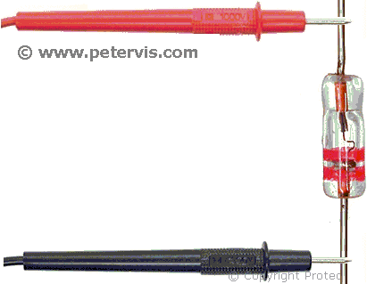
You need to connect the black probe of your meter to the cathode terminal. The cathode terminal is on the side with a band. You then connect the red probe to the anode terminal. If your meter is ON and set to the diode test mode, it should provide you with readings in volts. If the figure is 0.3 V or less, then the diode is a germanium type.
Sensitivity and Forward Bias Characteristics
The sensitivity of a diode to radio waves is said to depend upon its threshold voltage, which is also known as forward bias voltage (Vf) in documentation. This is the voltage across the diode terminals, and when it falls below this threshold value, the diode will stop conducting. Obviously, the lower this threshold value is, the greater the sensitivity of the diode to weak radio signals. An ideal diode would continue conducting even with the smallest and weakest signals from a distant radio station, and therefore, such a diode would be able to detect many radio stations.
| Diode | Forward Voltage -- Vf (V) |
| AA117 | 0.18 |
| OA90 | 0.25 |
| 1N3287 | 0.3 |
| 1N949 | 0.39 |
| G1607 | 0.45 |
| OA47 | 0.45 |
| AA139 | 0.5 |
| 1N91 | 0.5 |
| AA135 | 0.75 |
| AAZ18 | 0.75 |
Here are some threshold voltage estimates for a random set of diodes. I have only ever tried the OA90, which tends to be readily available, and seems to work very well.
This Article Continues...
Making a Crystal Radio Electronics LabMaking a Crystal Radio - The Little Whippersnapper's Parts List
Crystal Radio Baseboard 4-inch by 12-inch by 1/2-inch
No. 6 Brass Screw Cups & No. 6 Screws 1/2-inch
Marking Out the Baseboard and Installing the Screws
Making the coil
Crystal Radio Coil
Crystal Radio Coil Winding
Crystal Radio Coil Terminals
Connecting the Crystal Radio Coil
Main parts
Crystal Radio Diode
Germanium Diode Test
Crystal Radio Earphone
Crystal Radio Circuit
Crystal Radio Specification
Optional
Potentiometer Mounting Bracket
RFC - Radio Frequency Choke
Project Power Supply Wiring
10k Potentiometer Wiring
BC549C Lead Extensions for Future Amplifier Projects
Wiring the Speaker to the LT700 Transformer
Credits
The Little Whippersnapper's Radio
