TA7642 Circuit Build
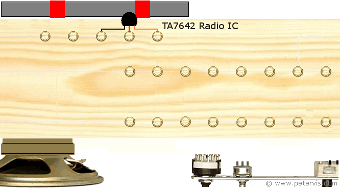
Installing the TA7642 IC into the circuit was very simple. Its terminals were short; therefore, I used the sockets from a breadboard ribbon cable to extend them, as shown in the BC549C Lead Extensions page, which is part of Making a Crystal Radio article. If you have not seen it then you will have to go over it. I am using the black wire for ground, the centre red wire is input, and the orange wire is output. They simply screw into the screw-cup connecting system as shown above.
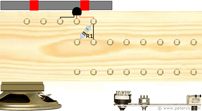
Install resistor R1, which is a 100 kΩ value. This resistor controls the Automatic Gain Control of the IC.
Also, install the link shown by the black line.
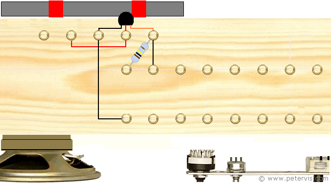
Connect the circuit links shown by the black and red coloured lines.
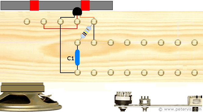
Install capacitor C1, which is 0.01 µF in value. This capacitor connects in any direction. You can find more information about capacitors in the Standard Capacitor Values article. If you are using recycled capacitors then the Capacitor Marking chart might help. It has the values for the complete range.
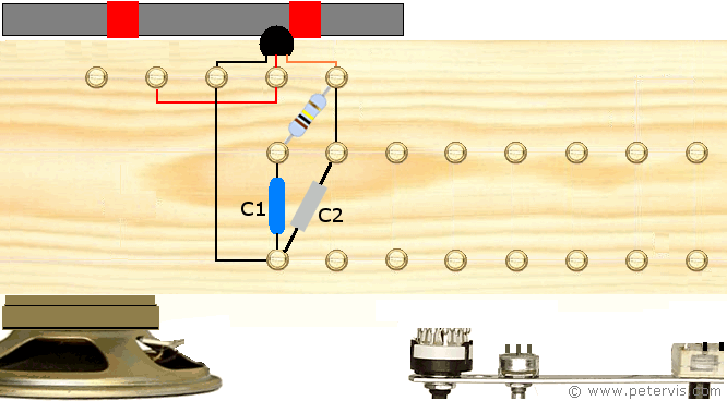
Install capacitor C2, which is 0.15 µF in value.
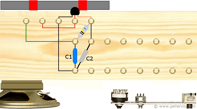
Install the wires to the Ferrite Coil shown above by the green line.
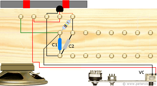
The next step is to connect the variable tuning capacitor. If you are using a different one then you will need to consult the documentation for your component. Alternatively, my Tuning Capacitor page might help. You need the wires to be straight and not twisted. It must be as short as possible. You could also use a screened coaxial to prevent any crosstalk.
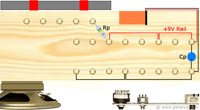
At this stage, we install some more components and wires to the build. To keep the diagram above simple, I am not showing the previously installed components. Install the power resistor Rp. In my build, I am using a resistor with a value of 150 kΩ.
Install the electrolytic capacitor Cp. I am using a 470 µF / 10 V value because this is all I had in my recycle box. If you are getting motor boating or oscillation noise, then you could try other higher values. Originally, I did not have a capacitor Cp across the power rails, and when I turned the volume clockwise, I was getting an awful motor boating sound. The 470 uF capacitor across the power rail soon sorted that. You could try lower values; however, I did not want to hear that sound ever again!
Install the power rails shown by the black and red lines. You need to wire the rails like this because the LM386 chip, which you will install later, will also be able to use it.
Assuming the ferrite coil, selector switch, antenna, and earth are present and operational, and you have not missed anything critical out, you should be able to hear the radio signal from the output pin 3 of the IC. However, you will need to use your crystal earpiece at this point because the signal is very small and weak.
This Article Continues...
TA7642 AM Radio - Project TomTA7642 AM Radio Baseboard Construction
Ferrite Coil
TA7642 Ferrite Coil Connection
Radio Stage
TA7642 AM Radio IC
TA7642 Power Resistor Rp
TA7642 Circuit Build
Amplifier Stage
LM386 Amplifier - TA7642 AM Radio
LM386 Circuit Build
Misc
TA7642 Circuit
TA7642 AM Radio Parts List
TA7642 AM Radio Parting Shots