Gertboard DAC - Digital to Analog Converter: MCP4802

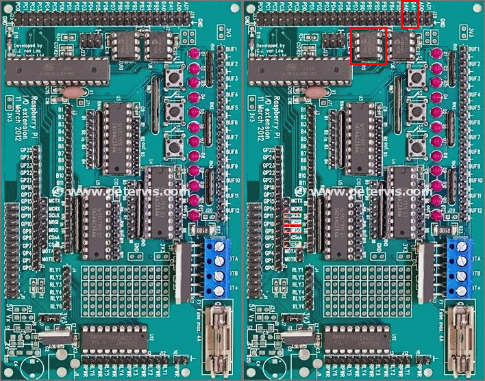
MCP4802 is a two-channel 8-bit precision digital-to-analogue converter (DAC) IC marked as U10 on the Gertboard. This IC receives digital signals from the serial peripheral interface (SPI) and converts them to analogue signals, which emerge from either DA0 or DA1. If you are new to SPI communications, then the Serial Peripheral Interface article will be useful for understanding the basics.
Configuring DAC Jumper Pins

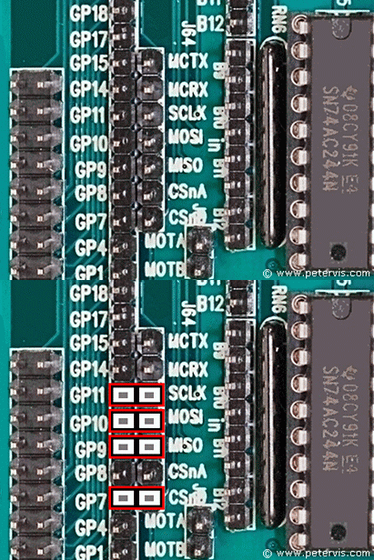
If you were wondering how to configure the DAC jumper pins, then this part will help. Simply place jumper links across the following pairs of header pins.
- GP11 to SCLK
- GP10 to MOSI
- GP9 to MISO
- GP7 to CSnB
The GP11, GP10, GP9, and GP7 pins have an alternate function for SPI communication.
Circuit Diagram

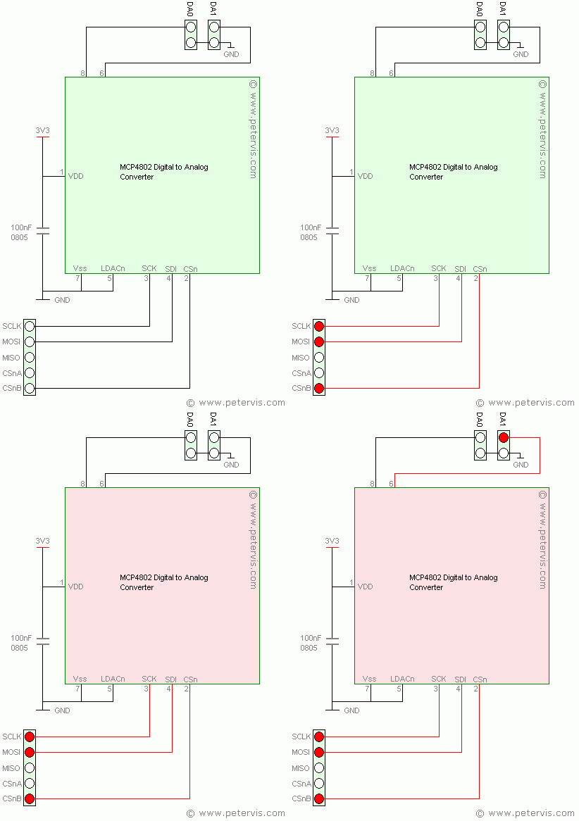
This circuit diagram shows how the MCP4802 DAC IC connects to the header pins. The Raspberry Pi sends the digital data through the SPI to this IC. It then converts it to an analogue signal, which manifests at either DA1 or DA0 pins. In this example, the sound is mono as only the DA1 channel provides the output. The analogue output range is between 0 V and 3.3 V. This signal is analog in nature and a moving coil meter can read its value.
This Article Continues...
Gertboard Raspberry Pi ExpansionGertboard Buffered I/O: SN74AC244
Gertboard Open Collector Drivers: ULN2803APG
Gertboard Motor Controller: L6203
Gertboard ATMega Chip: ATMega168A/PA, and ATMega328/P
Gertboard ADC - Analog to Digital Converter: MCP3002
Gertboard DAC - Digital to Analog Converter: MCP4802
Gertboard GPIO Pins