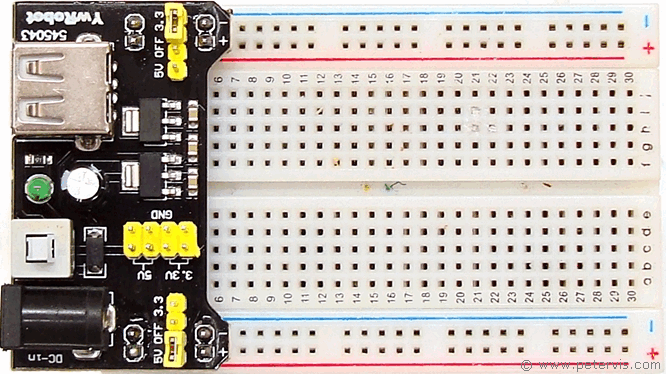
How to Use a Breadboard Power Supply
Using a breadboard power supply is extremely simple, and in this article, we cover some simple and basic tips to help you get started using this commonly available and low-cost circuit board. There are many different types of boards at varying prices, however I am using the cheapest that I could afford on eBay made by YwRobot. In the previous sections, I wrote about the suitable input voltages required and how to power it using a suitable adapter. Assuming you already have such a suitable adapter and are providing the correct input power through the barrel socket, then we can focus on connecting it to a commonly available low-cost breadboard.
Assuming you are applying the correct voltage, when you press the switch to the ON position, you should see the LED light up. Whilst it might be delightful for you, as professionals, we must measure the output voltages first to make sure they are correct. The following sections explain how to do this.
Installing the Circuit Board
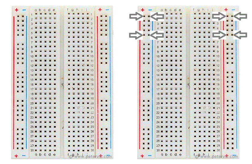
You can install the circuit board on either end of the breadboard, however, where the row begins with "1", is the ideal end. In this diagram, you can see exactly where the pins on the reverse of the circuit board connect on the breadboard.
It is important to install it at the correct end, because then the positive and negative voltage rails on the circuit board will match the coloured lines on the breadboard. Hence, the positive rail will have a red line next to it and the ground (Gnd) will have a blue line. It is so simple, but good practice, because you will be amazed how many times the "professionals" get it wrong.
Configuring Voltage Jumper Pins
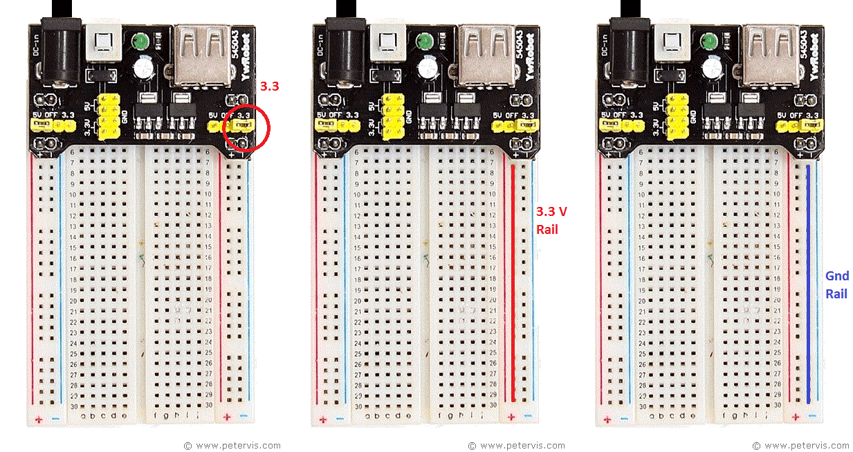
On the circuit board, there are jumper pins so you can select the voltage rails you require. In this case, I am choosing 3.3 V and 5 V rails. On the animated diagrams, you can see which side of the rails are for 5 V and which are for 3.3 V, based on the jumper pins.
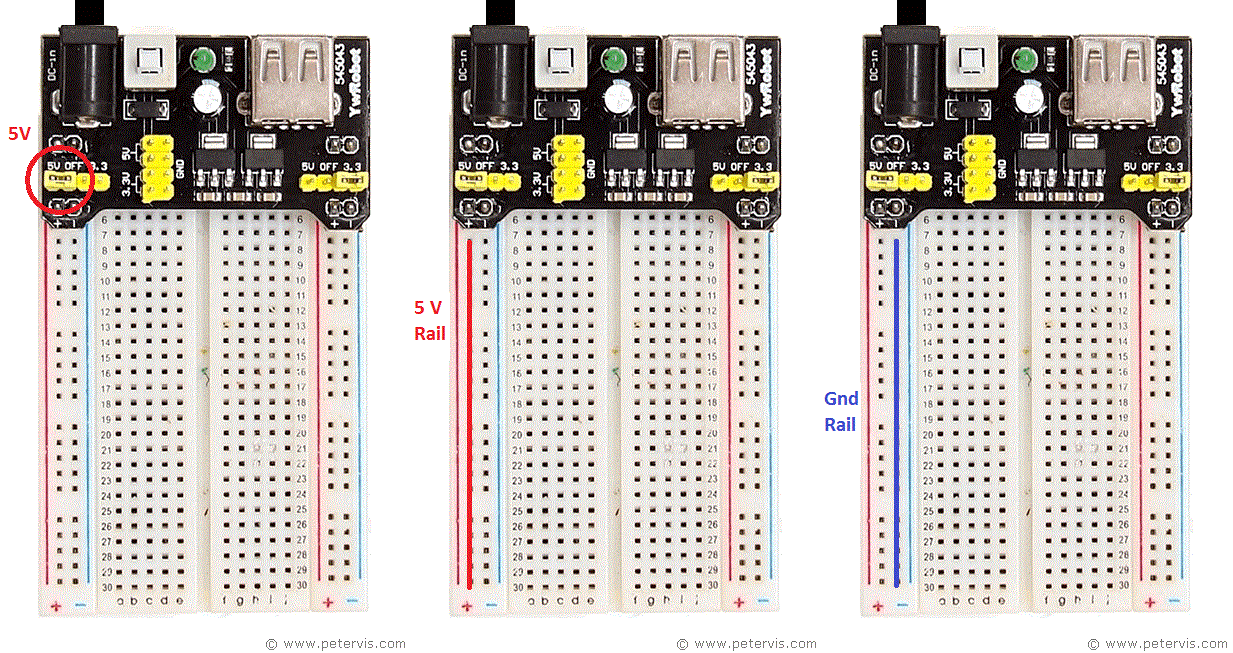
Before you start building a circuit, connect some jumper wires, which ideally should be single core copper stripped at the ends and see if you can measure the voltages. If you are using a low-cost digital meter, then it could be set to 20 V DC range to measure the voltages. Insert the wires along the holes on the breadboard to satisfy yourself that there is indeed a voltage along those lines. Once you have verified that there is indeed the correct level of voltages at the correct locations, then you can start building your circuit.
LED Test Circuit
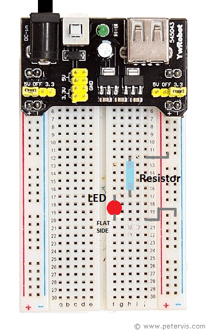
Perhaps a first exercise and test circuit would be to light an LED from the voltage rails. If we wanted to light an LED from the 3.3 V rails, then we would need a standard LED that has a forward voltage drop of 1.7 V. These are the standard cheap ones readily available at places such as eBay in bags of 100.
You will also need a voltage drop resistor to connect in series with the LED. The resistor has to be around 800-ohms or thereabouts, and these are also cheap and readily available in bags. The colour code is grey-black-brown-gold. The wattage is not so critical and can be ¼-watt, or anything going cheap, providing its leads can be inserted into the holes.
When installing the LED you will need to identify one side of it that has a flat edge. LEDs will only work in one direction so pay special attention to the lead near the flat edge.
I hope this extremely simple article was clear and useful enough to start you off on the royal road to using a power supply circuit board.
