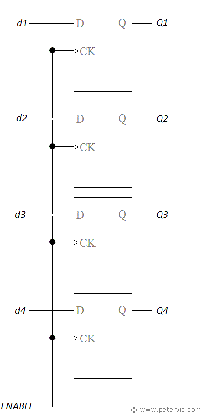
4 Bit Data Latch

Here is a 4-bit data latch using D-type flip-flops, and with tri-state capability. A latch is simply a temporary binary data storage facility to store bits. A four-bit latch uses four D-type stages to store them. An eight-bit latch has eight stages joined in the same way. In this circuit implementation, we tie the clock inputs together, and this then becomes the ENABLE control signal. The sequence of operations required to store the data involves the following.
- Set the ENABLE control signal to HIGH.
- Send data to the D inputs.
- Set ENABLE control signal to LOW
When the enable control signal is high, data sent to the D inputs transfer to the Q outputs straightaway. We then set the enable control signal low to lock these bits so they do not change. They will remain locked as long as enable remains low. If the D inputs change, but enable is low, then the outputs remain the same. This is very useful in sample and hold circuits where the data from an external system may be changing and you wish to hold one sample for processing.
The term tri-state refers to the Q outputs being capable of having three states, which are logic 1, logic 0, and high-impedance. Latches are usually used in data buses to control the flow of data in a shared bus. When two subsystems wish to share the same data bus, one system sets its outputs to high impedance, whilst the other system uses it. This minimizes noise in the bus, and ensures the electrical current flows in the correct direction.