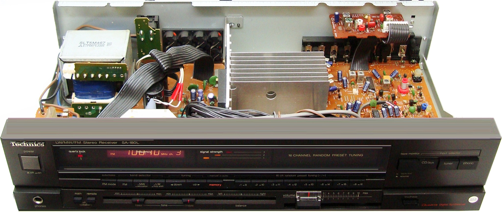
Technics SA-180 Repair


Repairing the SA-180/SA-180L is extremely complicated and not for the faint hearted engineer. It requires someone who is not just a qualified engineer, but has extensive engineering experience. These notes are for the hardened engineer and not for the hobbyist. If your amplifier needs repair, then there are many online firms on Google offering repair services. The ones at the top are usually the best!
Let there be light... I love buying broken amplifiers on eBay and when I bought this SA-180L, I thought finally my luck had changed and it would be one with a simple problem of a crackling volume control knob... Or so I thought, until I plugged it in and found it to be completely dead. As an engineer, I first measured the AC output on the secondary of the transformer and all the rails were present and correct. I checked the DC output from the bridge rectifier and that was present and correct as well.
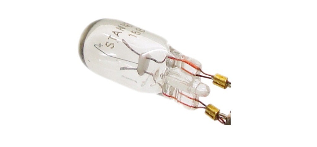
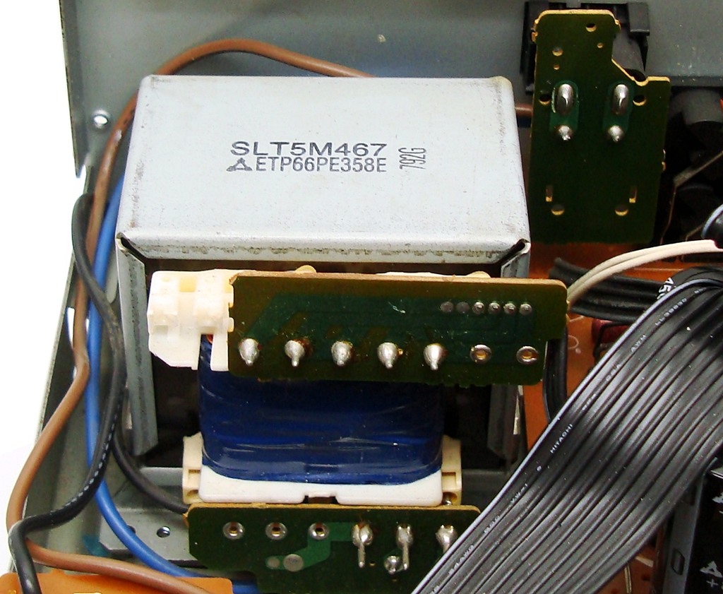
The light bulbs should illuminate straight away when switching ON, but on this amplifier, there was no illumination! The 11.5 V on pin 4 of the secondary was there so I checked the bulbs and sure enough the filaments on both bulbs were open!
In this amplifier, they use one bulb for the LCD backlight illumination and another for the power switch illumination. These bulbs connect in parallel and are powered directly by an 11.5 V AC tap on the secondary side of the transformer. As you can imagine, as soon as you switch ON the amplifier, these lights should illuminate. On my amplifier, both bulbs had failed giving the appearance that the amplifier was dead, when in fact it was receiving power and the circuits were operational, up to a point. The bulbs are marked STANLEY 12 V 0.15 A. These are filament bulbs and unfortunately I could not find any identical ones for replacement, therefore I decided to see if there were any torch bulbs. I managed to find one bulb rated 12 V 0.2 A hence decided to use that. I decided to replace just one bulb, for the LCD backlighting. The other bulb for illuminating the power switch was not necessary so I left that as it was.
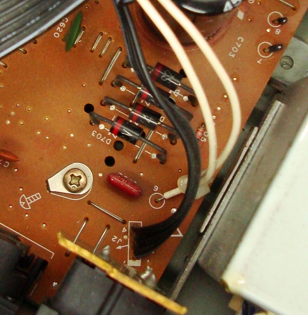
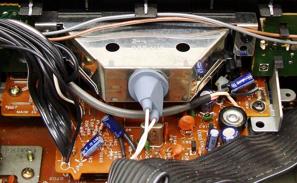
Being a Brit, changing just the bulbs left me feeling rather omnipotent, and I had not even checked the electronics yet! The first problem I noticed was that there was no LCD reading on the display so I knew that this was an ominous sign of something more to come... Continuing from the bridge rectifier, the positive voltage goes to Q701 and the output (at the emitter junction) was approximately 15.1 V, hence that was correct. This voltage then goes to Q703 which establishes the 5.5 V rail, and here there was a problem as there was no 5.5 V present. Looking on the component side, I located the transistor under a plethora of ribbon cables and noticed that somehow it was twisted and bent such that its terminals were joined and shorted. Hence I straightened its terminals and applied some fresh soldering to its junctions. After fixing that, the LCD and everything else came back to life again.
After the first miracle, I decided to connect a pair of headphones to see if there was any sound coming from the amplifier, and sure enough one channel was working, but the other was intermittent. Here the problem seemed to be with the slider volume control because at some points along the track both channels operated. Looking closely at the slider volume control, I noticed that someone had applied a huge amount of grease to the tracks. Grease will prevent an electrical connection to form, and that was the problem, hence I spent the next half-hour removing the grease with tissue paper, and cleaning the whole slider with an electrical contact cleaner. After cleaning, it began to work normally and I was hearing sound on both channels however one side was always too low and slightly distorted even after adjusting the balance.
After the second miracle I decided to take a break as half the day was gone in dismantling, soldering, cleaning, and tracing the circuit diagram... However the good news was that the amplifier was clearly off the critical list and well on the way to a good mend.
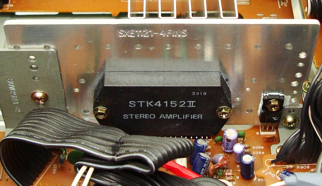
After breaking some bread and water, as that is all that a blogger can afford these days, I figured it would be a good idea to measure the DC output of the STK4152 II hybrid IC. One channel was reading +0.002 V DC, which is negligible, however on the other channel I was getting -13 V DC. Not only was it an unlucky number but very unlucky for me as it meant that the IC was faulty and would need replacing. Replacement ICs are available on eBay but they can be expensive as it is old stock, and the very cheap ones from China are often fakes. The only other alternative was to visit my friend Rufus. Rufus has his own night club and has killed many amplifiers in his time, and usually he keeps a shed load of his favourite amps that he expects me to repair for him. As soon as he found out that I had this vintage amp, he wanted it. Hence the deal was that he would supply a working IC, and after I repaired it, he would buy it off me.
Within 24-hours, Rufus managed to get a replacement IC and delivered it personally in his Ferrari. He could not wait to take the amplifier with him and decided to hang around whilst I soldered it in. Just as the last screw was in, he snatched it off my hands, threw some money, and all I heard was the car screeching away. Well, that is Rufus for you...
This Article Continues...
Technics SA-180Repair
Engineering
Tuner Circuitry
Back Sockets