Transistor as a Switch Biasing

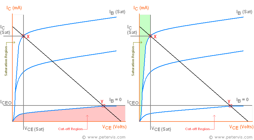
Biasing a transistor to operate as an ideal switch involves understanding transistor characteristics graphs. This article focuses exclusively on biasing and if you have "gaps" in your knowledge, then I recommend reading the earlier pages of this multi-page article. When a bipolar junction transistor (bjt) behaves as a switch, it is an accepted textbook convention, which states that the transistor must operate within the saturation and cut-off regions of the graph.
When the current to the base junction is sufficient, it conducts in the saturation region operating within the shaded active region. When the current to the base is insufficient, its operation is within the cut-off region and the transistor no longer conducts.
Saturation
When a bjt behaves as a switch, it operates in a saturated condition, which is when the resistance across the emitter-collector junctions is almost zero. When this happens, there are three things to note.
- The collector current Ic will be at maximum level, which is the level the load requires. We calculate the value of required current using Ohm's law.
- At saturation, further increases in base current will not increase the collector current.
- The voltage between collector and emitter is zero or negligible, which results in Vcc across the load RL.
Base Resistor Calculation

Biasing the transistor with the correct base resistance ensures that it operates within the saturation region. It is required to be fully conducting thereby exhibiting a minimum voltage drop across Vce.
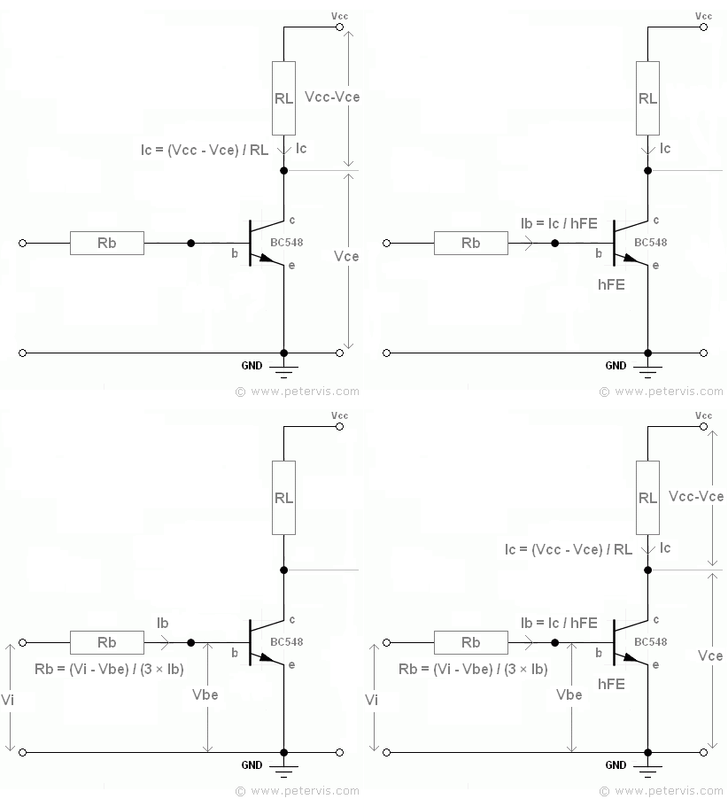
Here is a simple common emitter circuit typically found in most textbooks and data books. A "common emitter" circuit uses the emitter junction as a common for the input and output. The transistor behaves as a switch to ground, because when the transistor is conducting it provides a ground path to the load (RL).
Formula to Find Base Resistance
To calculate the value of the base resistor, first find some parameters from the reference information of the transistor that you are using. In this case, I am using a BC548 with the following parameters.
- Vbe (ON) = 0.77 V
- Vce (SAT) = 0.25 V
- hFE = 110
As you can see, hFE is the DC current gain of the transistor, and the following formula describes the gain in terms of collector current, and base current.
Ic = hFE × Ib
From the diagram above, we can see that the current across the load RL is Vcc - Vce, where Vcc is the supply voltage. Therefore, Ohm’s Law dictates that the current Ic passing through it must be given by the following formula.
Ic = (Vcc - Vce) / RL
This is the amount of current passing through the load, which also must be within the Ic (MAX) parameter of the transistor. For the BC548 the absolute maximum rating is 500 mA.
The voltage across the base resistor is given by Vi - Vbe, and the current flowing through it Ib. Therefore, using R = V / I, the following formula is derived.
Rb = (Vi - Vbe) / (3 × Ib)
To ensure that the transistor operates within the saturation region Ib is multiplied by a factor of three.
Example Calculation
Let us say that the load is a typical 5 V relay with a coil resistance of 69.4 Ω. You decide to use the transistor BC548.
You have a 3.3 V signal from an Arduino microcontroller or a Raspberry Pi to drive the base junction of the transistor, hence Vi = 3.3 V. The transistor circuit is powered by 5 V, hence Vcc = 5 V.
What is the correct value of the base resistance Rb that will make the transistor conduct fully and operate within the saturation and cut-off regions?
- STEP 1: Calculate Ic
- Ic = (5 - 0.25) / 69.4
- Ic = 0.068 A
- STEP 2: Calculate Ib given that hFE = 110
- Ib = 0.068 / 110
- Ib = 0.00062 A
- STEP 3: Calculate Rb
- Rb = (3.3 - 0.77) / (3 × 0.00062)
- Rb = 1360.21 Ω
Looking at the Standard Resistor Values chart the nearest value is 1200 Ω. The Transistor Base Resistor Calculator performs the same mathematics to save some time.
Related Articles
The TransistorTransistor as a Switch Biasing
Darlington Transistor
Phototransistor
Transistor as a Switch Using LDR
Metal Oxide Semiconductor Field Effect Transistor (MOSFET)
Using a Transistor to Drive a Motor
Transistor Circuit to Drive LED
Transistor as a Switch for Relay
Transistor as a Logic Switch
Transistor as a Switch PDF