555 Astable Flashing LED
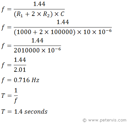
Here is a 555 astable circuit, which behaves as an oscillator where the output pin 3 will periodically go high and low causing the LED D1 to blink. In this circuit, R1, R2 and C1 components determine the timing of the oscillator. We can calculate the frequency using the standard formula for astable configuration.

LED and R3
The value of R3 depends upon the supply voltage. If for example the supply voltage were to be 9 V, then HIGH output from pin 3 will be close to 9 V. If you are using a standard red coloured diode with a forward voltage of 2.1 V, then R3 would be approximately 345 Ω or thereabouts. You should use my LED resistor calculator for more information.
Related Articles
555 Timer Driving LED555 Astable Flashing LED
555 Timer Dual LED Flasher
555 Astable with Dual Flashing LEDs
