Crystal Radio -- Budget Cuts 140-pF
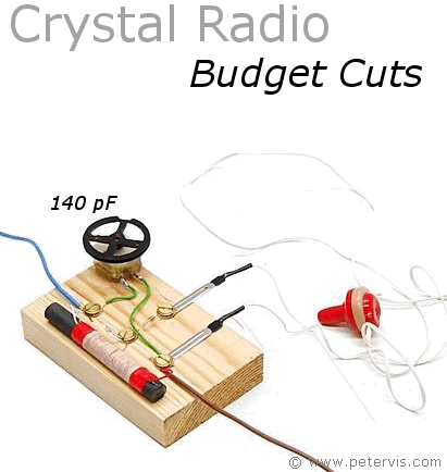
This crystal radio design is based on the cheaper 140-pF variable capacitor and consequently it is named budget cuts. Back when I was a whippersnapper, I experimented with the 140 pF variable tuning capacitors and managed to design a great circuit that worked, and you could tune into all the stations as well! I found all of my old projects in the shed and figured I had better publish them because there seems to be a real lack of information about crystal radio circuits using this tuning capacitor.
I managed to make a nicely tuned ferrite coil that all whippersnappers can make to use with the cheaper 140 pF tuning capacitor. These capacitors cost as little as a pound on eBay, but unfortunately, there is not much information on how to use them properly with crystal radios. Everyone will tell you to increase or decrease the turns in the coil, but not how much or even which circuit to use. Hence, I decided to carry out some research, which will help everyone who wants to make a crystal radio and use the cheaper 140 pF tuning capacitor.
Circuit Diagram
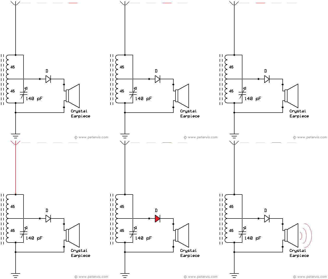
In this circuit, the signal to the germanium diode comes from the centre tap. The signal at that location changes the most. The mathematics for this is beyond the scope of this article; however, if I get the time, and if this article gets any hits, then I might add some pages in The Beauty of Mathematics section.
I designed the circuit like this because it is forgiving if you make a mistake with the number of turns, or the coil type used. You could have up to a maximum of 50 turns on either side of the tap, and that will have the effect of widening the AM coverage, and still allow you to tune into the stations. In this particular circuit, and on this occasion, I have chosen 45 turns of coil on either side of the tap, because it then provides good coverage of BBC Radio 4. This is the optimum setting for the coverage of this station. I was also able to receive Radio 1035 AM, which appears to be flooding the airwaves in the Croydon area. If you are a fan of this station, then this crystal receiver will easily detect that station, and you should make it!
Circuit Layout
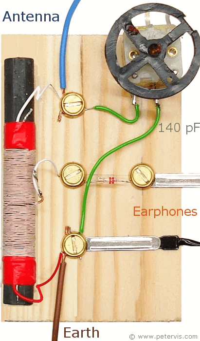
Here is a photograph showing the circuit layout and build. As you can see, the centre tap connects to the germanium diode. The metal strips show where my vintage crystal earphones are connected.
Ferrite Coil
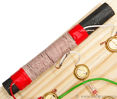
In this ferrite coil, there is only one centre tap, with exactly 45 turns of Litz wire coiled on either side. One end of the coil connects to the antenna, and the other end to the earth. The 140 pF tuning capacitor goes across the coil, between antenna and earth, as always. The only difference is that the signal to the germanium diode comes from the centre tap. I bet none of you 'radio experts' ever thought of doing it like that.
Germanium Diode
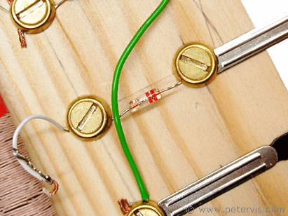
You will need a good quality germanium diode for this circuit. Please refer to the Crystal Radio Diode page for more information.
Summary
If you build the ferrite coil exactly as stated, you should get a good tuning range using the cheap 140 pF tuning capacitor. Enjoy!
Related Pages
Spy Crystal RadioCrystal Radio -- Budget Cuts 140-pF
One Transistor Radio