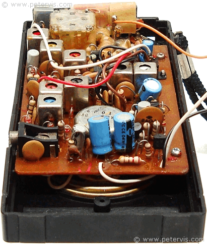
Ingersoll Pocket Radio inside Look
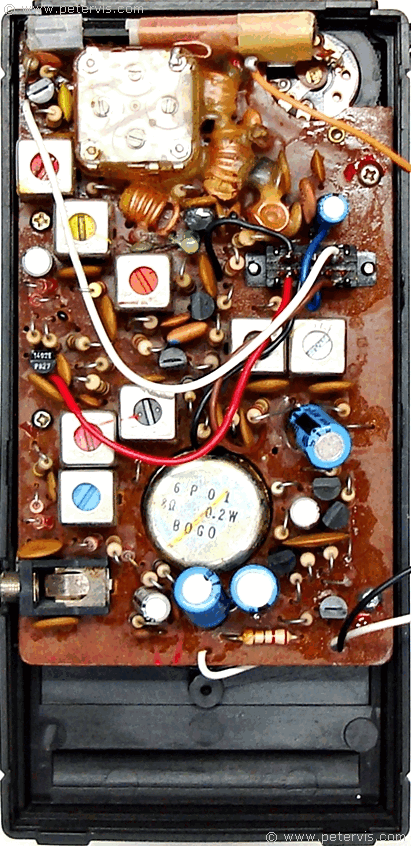
This Ingersoll pocket radio has eleven transistors, and ten diodes, and the circuit has extremely good reception. Being a deluxe version, the circuit design is to a high specification.
Looking at the circuit diagram, we can see that transistors 9013 (Q10) and 9015 (Q11) form a Class AB complementary Symmetrical Output Stage, which drives the loudspeaker. The preamplifier stages consist of 9014 (Q8, Q9) transistors, which are for low-noise preamplifier applications.
In the radio circuit, there are three 9016 transistors, which perform AM conversion and AM/FM amplification. There is a 9018 transistor for the local oscillator, and VHF/FM tuner application.
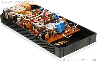

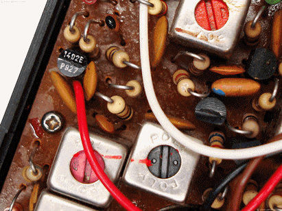
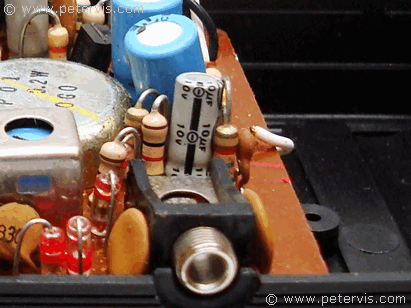
This Article Continues...
Ingersoll Pocket RadioIngersoll Pocket Radio inside Look
Ingersoll Pocket Radio Variable Capacitor and Ferrite Coil
Ingersoll Pocket Radio Power Supply
Ingersoll Pocket Radio Box
