National Panasonic T-100D Repair
The National Panasonic T-100D was completely dead, and did not produce any sound from the loudspeaker. I connected my headphones in the headphone socket and heard a very slight hiss indicating that perhaps the audio amplifier stage was just alive but barely. Unfortunately, I was unable to obtain a circuit diagram for this radio, however, this Japanese heterodyne design is very straightforward, and I decided to rely only on my diagnostic skills to figure out what was wrong.

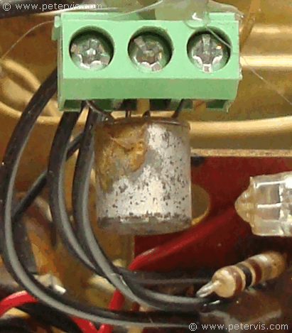
The trail began with transistor 2SA70 which is a PNP germanium transistor in a TO-70 package. The radio frequency (RF) signal enters the printed circuit board through a wire and passes through the first stage, which has this transistor. I was vaguely familiar with the 2SA70 and knew they are usually found in mixer, oscillator, and intermediate frequency (IF) stages of radio circuits.
I decided to measure the voltages at its terminals and note them down on scrap paper.
- Emitter 2.37 V
- Base 2.07 V
- Screen 1.82 V
- Collector 2.07 V
Based on my semiconductor knowledge, and looking at these voltages, I could see that they were screwy. I would have expected at least 4 V to 5 V at the collector, but it was half of what it should be. I was getting 2.07 V on the base and collector, which was leading me to think that there, may be in internal short in this transistor.
From experience, I knew that heating the terminals of these old germanium transistors could sometimes clear their internal short. Therefore, I simply applied some fresh solder to their terminals, and the transistor came back to life again.
My Antex ES soldering iron uses ceramic technology, which provides electrical insulation allowing me to work on current carrying circuits. Hence, as soon as the transistor terminals heated, the short cleared and I could hear a faint radio signal through my headphones. Therefore, I replaced the 2SA70 with an AF116, and that worked extremely well.
Fuzzy Low Volume Audio

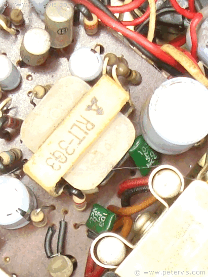
The second problem was with the very low volume fuzzy sound. The power output stage is a Class B Push-Pull type utilising a matched pair of 2SB324 PNP transistors mounted to the metal chassis. I decided to check the voltages at their terminals and both transistors had identical values. Either both were faulty, or both were working below established parameters.

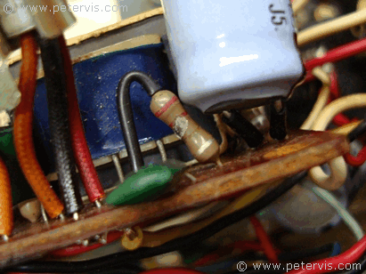
In this type of configuration, the emitters of both transistors usually join to a common voltage rail, whilst the collectors drive the primary winding of a transformer to recombine the opposing phases of audio. Usually the drive is close to supply rail, and therefore I would have expected approximately 7 V at the emitter, however it was only 3 V. In this circuit, the emitters receive current through a common resistor. Whilst looking at this resistor closely to determine its value, I noticed a dark mark on the body indicating damage caused by overheating. A meter test indicated that the resistor was close to going open. It should have been a one-watt type, but instead they used a ¼-watt type, which is probably why it failed. Usually these resistors are low in value at around 2.2 Ω, so I replaced it with a higher wattage 2.2 Ω type and the radio came back to life again!
As you can see, even without a circuit diagram, it is possible to repair a circuit. The main thing is to get all the facts using a good measuring instrument, and then apply the logic. Of course, I can do this all day long, and make it look easy.
This Article Continues...
National Panasonic T-100DNational Panasonic T-100D Review
National Panasonic T-100D Circuit
National Panasonic T-100D Renovation
National Panasonic T-100D Loudspeakers
National Panasonic T-100D Sockets and Connections
National Panasonic T-100D Battery and Power Supply
National Panasonic T-100D Repair
National Panasonic T-100D inside Look
Radio Tuning String
National Panasonic T-100D Case
National Panasonic T-100D Dial Light Bulbs
National Panasonic T-100D Radio Chassis
