Driving LEDs by CMOS or TTL Outputs

A CMOS or TTL logic output can easily drive an LED through a series resistor. If you have already experimented with driving a single LED through the General Purpose Input / Output (GPIO) pin of the Raspberry Pi, then the next stage would be to blink an LED through a buffer gate. In commercial applications, a buffer usually acts as a driver for an LED, as it can provide more drive current than the GPIO pins. If you are experimenting with PWM techniques to drive an LED directly by CMOS or TTL outputs, then you run the risk of damaging the output port circuitry on your Raspberry Pi or Arduino. A much safer way is to use a buffer to drive the LED, this way if you drive too much current through the LED, you will damage the buffer IC and not the expensive Raspberry Pi.
LED
In this project, I am using ultra high efficiency low current LEDs that I bought in a bag of 10 on eBay. These are usually 3 mm to 5 mm in size and will light when the current is as low as 2 mA. They can operate on a maximum current of 30 mA, and have a typical forward voltage of 1.7 V. Low current LEDs are available from almost all the online stores listed on the Google search page. All the major stores such as RS, Farnell, and Maplin listed on Google have them.
Driving an LED by a CMOS Output

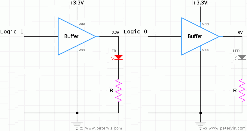
Here is a simple commonly found non-inverting CMOS buffer. The SN74AC244N is an octal buffer chip, which has eight of these buffers. The Cambridge Boffin: Raspberry Pi GPIO Buffer Project also uses this buffer chip.
With this IC, a single buffer can provide a maximum drive current of 6 mA which is not a lot. Luckily, this high efficiency LED can operate on as little as 2 mA, and I have decided to drive it with 3 mA of current leaving the rest for future projects.
Series Resistor Calculation 3.3 V

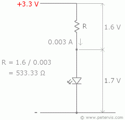
The calculation to find the value of the series resistance is very simple, and easy to follow. The 3.3 V output from the buffer drives the LED through a series resistor. Since the forward voltage of the diode is 1.7 V, the voltage across the resistor has to be 1.6 V. I have decided to drive the LED with 0.003 A, hence this current has to flow through the resistor as well, and the value of the resistor can be found using the formula shown below.
R = V / I
The value calculated was 533.33 Ω, and therefore using the standard resistors value chart the nearest standard value of 470 Ω works fine.
Driving an LED by TTL Output

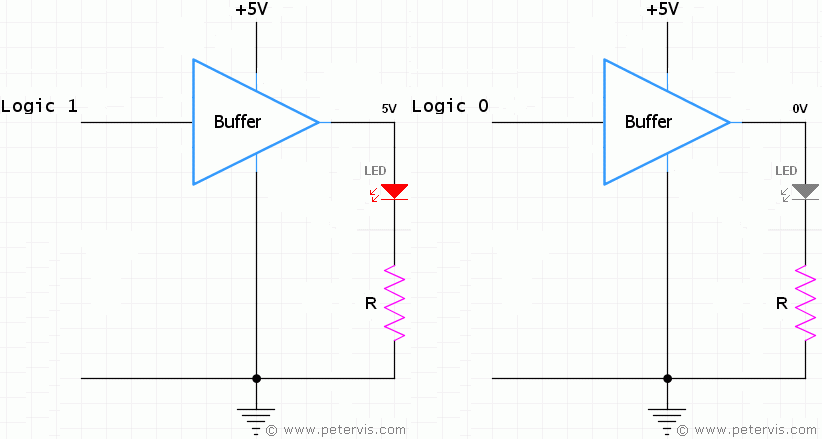
Many microcontrollers provide a TTL output from the port, which is close to 5 V. It usually has enough drive current to power a single LED through a current limiting series resistance. If your system is such as this then the following section shows how you could interface a single LED with a series resistor. You could also use a buffer to drive the LED, which will protect your microcontroller port. The 74HCT541 octal buffer chip is low cost and ideal for providing TTL outputs.
Series Resistor Calculation 5 V

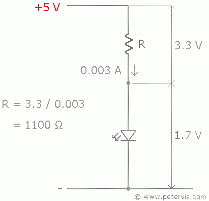
The calculation to find the value of the series resistance is same as before and simple. This time the drive voltage is 5 V and the drive current is the same as before of 0.003 A.
This time, the voltage across the resistor is 3.3 V, and therefore the resistance value calculates to 1100 Ω. Using the standard resistor values chart, the nearest value found was 1 kΩ which works fine.
This Article Continues...
Driving LEDs by CMOS or TTL OutputsDriving an LED using a Transistor
Current Sinking and Sourcing in TTL Circuits
Current Limiting Series Resistance Calculator for LEDs