4017 LED Warning Light

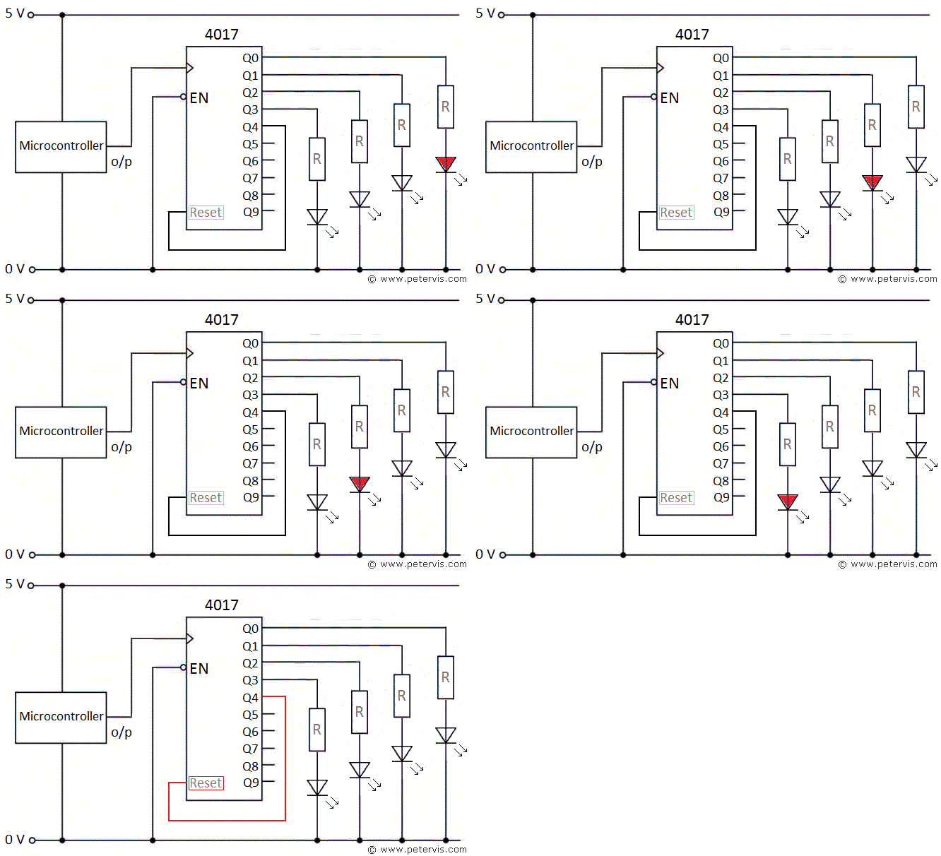
The 4017-decade counter can drive LEDs to form a chaser or sequencer type circuit. Here is a simple warning light application where the circuit flashes four LEDs one after another continuously. In this application, we use outputs Q0, Q1, Q2, and Q3 to drive the four LEDs, and output Q4 to reset the counter. By making the 4017 reset itself, it will flash the LEDs in a continuous manner. This IC also requires the enable pin (EN) to be LOW, and therefore we connect it to the 0 V rail. For the clock pulse, we are using a microcontroller; however, you could use a 555 timer IC just as easily.
The HIGH output of the 4017 will be close to the supply voltage, which is +5 V. If you are using standard red coloured LEDs with forward voltage of 2.1 V, then five volts across it is more than double the normal requirement and likely to damage it. Therefore, you must use a series resistor (R) of approximately 145 Ω to produce the required voltage drop.
A manufacturer usually uses Computer Aided Electronic Engineering (CAEE) techniques in the design of the circuit. It usually involves using a CAD package to draw the schematic diagram and PCB layout. These packages also produce the necessary data files for the production of the PCB. Another package may also be used to simulate the circuit to determine if the schematic and component values are correct. They usually design the plastic case using an engineering CAD package, which shows the drawing in 3D and produces the necessary data files so that a laser cutter may use to produce the required parts.
This Article Continues...
4017 Counter4017 Counter How Clock INHIBIT Pin Works
4017 Counter How RESET Pin Works
4017 LED Warning Light