555 Variable Oscillator Circuit

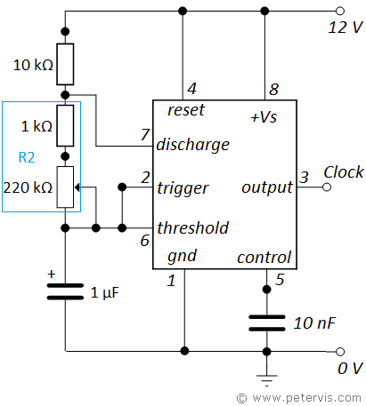
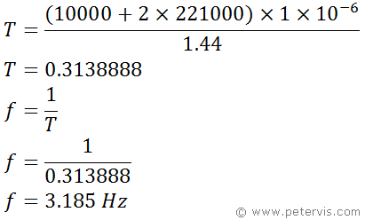
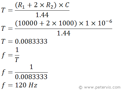
This variable oscillator circuit uses the 555 IC in astable mode to produce square waves. It is a variable frequency square wave generator, which allows the frequency to be set using a variable resistor. If you are building a stepper motor driver circuit, then you will need a square wave oscillator to feed the logic circuit. Usually, stepper motors require a very slow pulse therefore; I have designed this circuit to produce a frequency of 3.18 Hz when the potentiometer resistance is zero. This should be slow enough to produce approximately 1 rpm, depending upon the stepper motor you use. On the other extreme of the potentiometer (220 kΩ), the frequency will be 120 Hz, which would be fast enough for approximately 35 rpm.
Frequency Calculation

To calculate the frequency, we use this standard formula for an astable configuration.

Remember, that R2 is the sum of 220 kΩ potentiometer and 1 kΩ fixed resistor. R1=10 kΩ, and C=1 µF.

We now repeat for the same formula, except this time, the variable resistor is in the minimum position with zero ohms. This means that R2 is 1 kΩ.
Of course, you can adjust the component values shown in the 555 astable article to suit your specific needs based on the model of stepper motor you have. It is extremely simple to calculate the frequency because resistance R2 (in the formula) is a combination of the fixed 1 kΩ resistor and variable 220 kΩ variable resistor. The output of the variable oscillator circuit feeds the clock input of the stepper motor logic circuit as shown in the following articles.
This Article Continues...
Stepper Motor Driver Using MOSFETStepper Motor Logic Circuit
555 Variable Oscillator Circuit