Stepper Motor Clock Generator
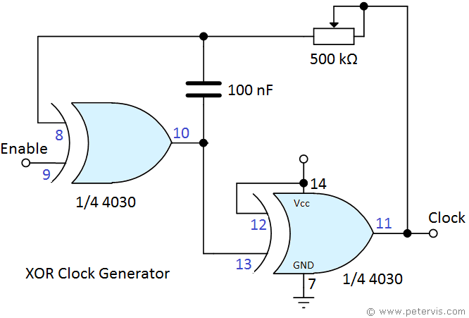
This circuit produces the necessary clock pulse for the D-Type Flip-Flops in the controller circuitry. Notice that both flip-flop stages receive the same clock pulse, and we use the remaining two XOR gates in the 4030 IC to achieve this. A clock pulse can generated in many ways using different gate types, however it is always more economical to use any remaining gates for this purpose than to use a 555 timer IC.
This circuit has a 500-kΩ potentiometer to control the frequency of the output pulse, which is useful if you need to change the speed of the stepper motor. The enable control switches ON or OFF the clock pulse, and behaves as a pause function would. A logic 0 state will enable it whilst tying it to the positive voltage rail disables it. Ideally, you will want to implement this with a locking switch.
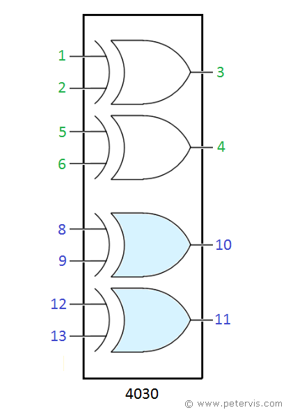
4030 Pinout

In this pinout diagram, the XOR gates in blue are used for the clock generator function.
This Article Continues...
Stepper Motor Logic Controller Using D-Type Flip-FlopsStepper Motor Clock Generator
Stepper Motor Driver Using Bi-Polar Transistors
