Split Rail Power Supply
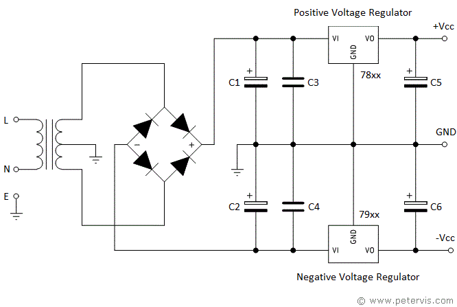
Building a split-rail power supply for op-amps is very simple, and requires a transformer with a centre tap on the secondary side. Dual power supply rails are very useful when working with op amps as this type of design provides greater stability. This article shows a generalised circuit, which you could adopt for ±5 V, ±12 V, and ±15 V designs.

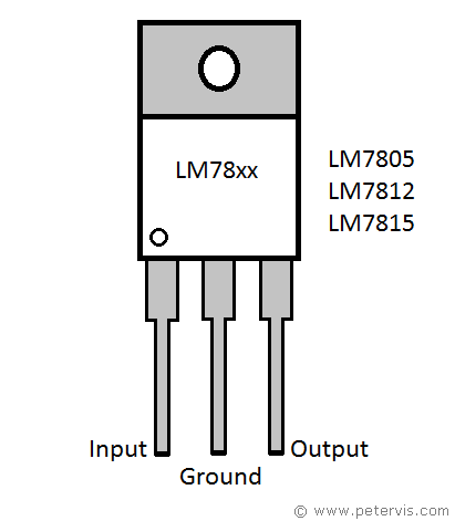
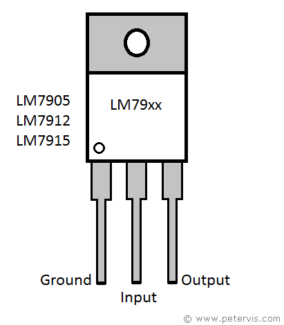
When installing the voltage regulators, pay special attention to the pinouts of the negative and positive voltage regulators. The centre pin of a positive voltage regulator is usually ground; however, the centre pin for a negative voltage regulator is input. This is usually where students make a mistake, in assuming, therefore it is wise to double check the documentation of the component you are using.

When choosing the transformer, you need to keep in mind that the absolute maximum input voltage for the LM79xx series is -35 V, and for the 78xx series, it is 40 V. Usually, 20 V DC input is sufficient for 15 V output.


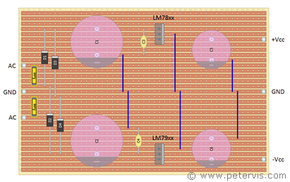
Of course, my first build was sublime and perfect with only two links that connected ground to the voltage regulator pins; however, it used axial electrolytic capacitors in the design. Unfortunately, axial capacitors are more expensive and therefore I decided to use radial ones, which is why I have the extra links. If you have a bigger pocket book, then get the axial types to save some time. If I had to mark this build, I would say it is near perfect, as there is not a single cut required anywhere on the board.
Components
| Component | Value |
| C1, C2 | 2200 µF |
| C3, C4 | 0.22 µF |
| C5, C6 | 100 µF |
| D1 – D4 | 1N4004 |
