12 V to 5 V Digital Signal Converter

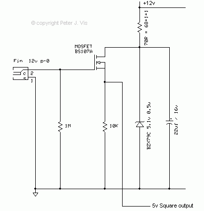
This circuit performs digital signal level translation by converting 12 V digital pulses to 5 V pulses compatible for use in TTL circuits. The tach signal from the Hall sensor circuitry first requires conditioning to the correct voltage level. Although the LM331 can accept an input signal up to Vcc level, I decided to condition it to five-volt level. I did it this way because for one thing the 12 V signal from the sensor circuitry may shift and deviate, and being so close to Vcc level may cause clipping. I would rather bring the signal to five-volt levels that way I can be sure it is within safe parameters.
The MOSFET transistor is powered by 5-volts, which is created from a 12 V supply using a Zener diode and series resistor because it is cheaper than using a 5-volt regulator. In this circuit configuration, a tach pulse at the gate junction will produce a +5 V pulse.
For more information regarding the value of the Zener diode and series resistance, I have a Zener Diode Series Resistor Calculator article that might help.
This circuit is very similar to the one in the Tach Pulse Multiplier article; hence please refer to that as well.
This Article Continues...
Frequency Multiplier using LM331 Chip12 V to 5 V Digital Signal Converter
LM331 Frequency to Voltage Converter Circuit
Op Amp Circuit with Gain 16
LM331 Voltage to Frequency Converter Circuit
5 V TTL Signal to 12 V Level Conversion
12 V Regulated Power Supply
Tach Pulse Multiplier Circuit Documentation