Understanding the WS0010 Font Table
The character code is essentially an address that selects the character that you want to display. Every character has a unique character code one byte long. Understanding how this number maps with the font table is important.

Here is a typical font table stored in CGROM memory that contains the character set. A two-dimensional array references the character within. The upper four bits of the byte select the column, and the lower four bits select the row. When you send a byte, consisting of four upper bits and four lower bits, to the WS0010 display RAM an automated function looks up the row and column in this font table and selects the character. Then another automated function called "Character Generator" reads the bitmap data and sets the dots on the physical LCD display according to the bitmap data.

If you want to display the character "A", you can see that the upper bits are LHLL, and the lower bits are LLLL, thus you would send the character code LHLLLLLL or binary "01000000" to the Display RAM. The great thing about this display is that you simply need to send it the character code byte, and the rest of the work of looking up the font table, reading the bitmap, and setting the dots on the display accordingly is performed automatically. This makes the programmers job much easier eliminating the task of manipulating the individual dots.
One of the reasons why people find this difficult to understand is because this is actually an array inside an array. The first array selects the desired character from the font table as shown above. The second array is the bitmap array describes the bitmap structure of the character. Once you have selected your desired character that you wish to display by sending the character code, an automated circuitry takes over and begins reading the second array, which is the bitmap array.
If you are using the factory installed character set in the CGROM, then it is no problem as you can see, however if you wish to use your own custom character set and fonts, then you will need to know the organisation of both arrays and how they link. This information helps to write the routines needed to load the CGRAM with your own custom font table. Luckily, the documentation shows a little of how that works, but very few understand.

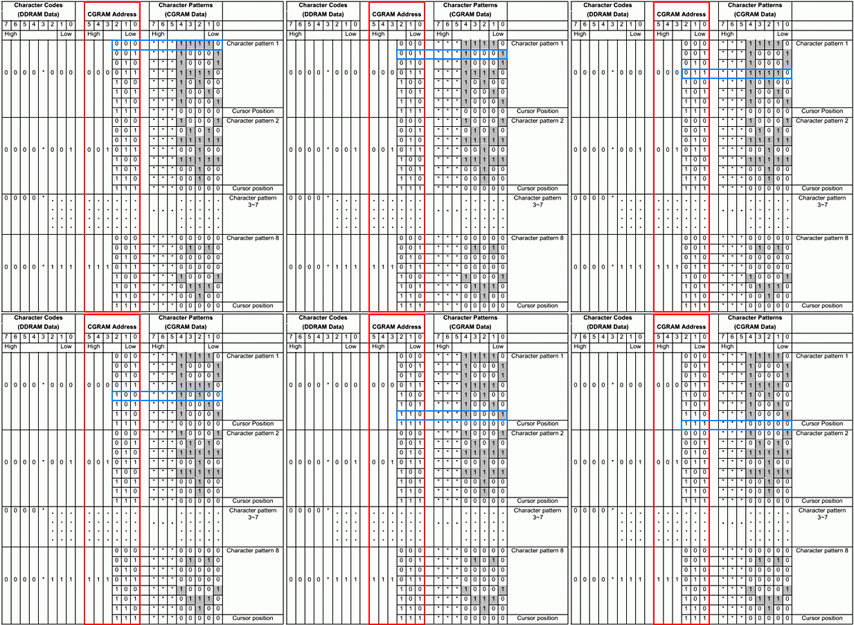
I call this the Rosetta stone diagram :-) because there are three things happening here and if you can understand them then the whole thing will make sense. The column highlighted in red shows the contents of the DDRAM memory. As explained earlier, this memory stores only character codes. As explained earlier a character code consists of eight bits where the lower four bits indicate the row, and the upper four bits indicate the column of the font table.
As you can see, bit 3 is not used, which means there are only three bits for the lower part of the byte, and four bits for the upper. Hence, the lower three bits can address eight rows in the font table and upper four bits address 16 columns in the font table. Therefore, permitting 64 characters in a character set font table. This is why the datasheet states CGRAM memory to be organised as 64 × 8-bits.

For the second part of our Rosetta stone, this column describes the CGRAM address. The CGRAM stores the font table, and inside the font table there is the bitmap information of each character. The CGRAM addresses indicated in red are never stored anywhere because it is the same set of repeating numbers counted by the lower 3 bits. It acts like a counter mechanism for addressing purposes, and automated by internal circuitry. Hence, everything highlighted in red appears to be automatic.
The bitmap of each character in this example consists of eight rows, where row 8 is reserved space for the cursor. Since there are only eight rows, only three bits count them. The lower three bits are for the row counting / addressing. Bits 3, 4, 5 are not used at all and simply behave as an index. Each address value can therefore select a row of bit-mapped data. Hence, for example, binary address 000000 fetches the bitmap data for the first row for letter 'R', which is "00011110". The address is automatically incremented to 000001, and then brings the second row of data and so forth up to row 7.
When displaying characters defined in the CGRAM, the addressing mechanism / counting is automatic just as it is was when using the CGROM memory; the programmer needs only to send the character code of the character he wishes to display. There is not much information available on how to load this part of the memory with a custom character set, or information on the data structure to use. Once you know the addressing and data are organisation, the same principle of addressing stores bitmap data within the CGRAM. I hope this was useful for anyone learning how to use a WS0010 based display panel.
This Article Continues...
Winstar WS0010WS0010 Memory Organisation
Understanding the WS0010 Font Table
WS0010 Datasheet