9V Power Supply Circuit With Voltage Regulator
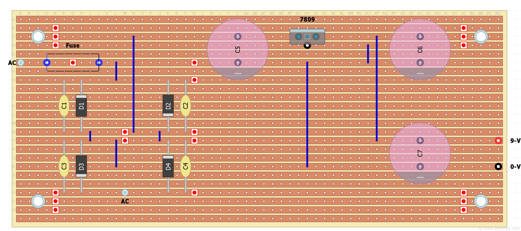
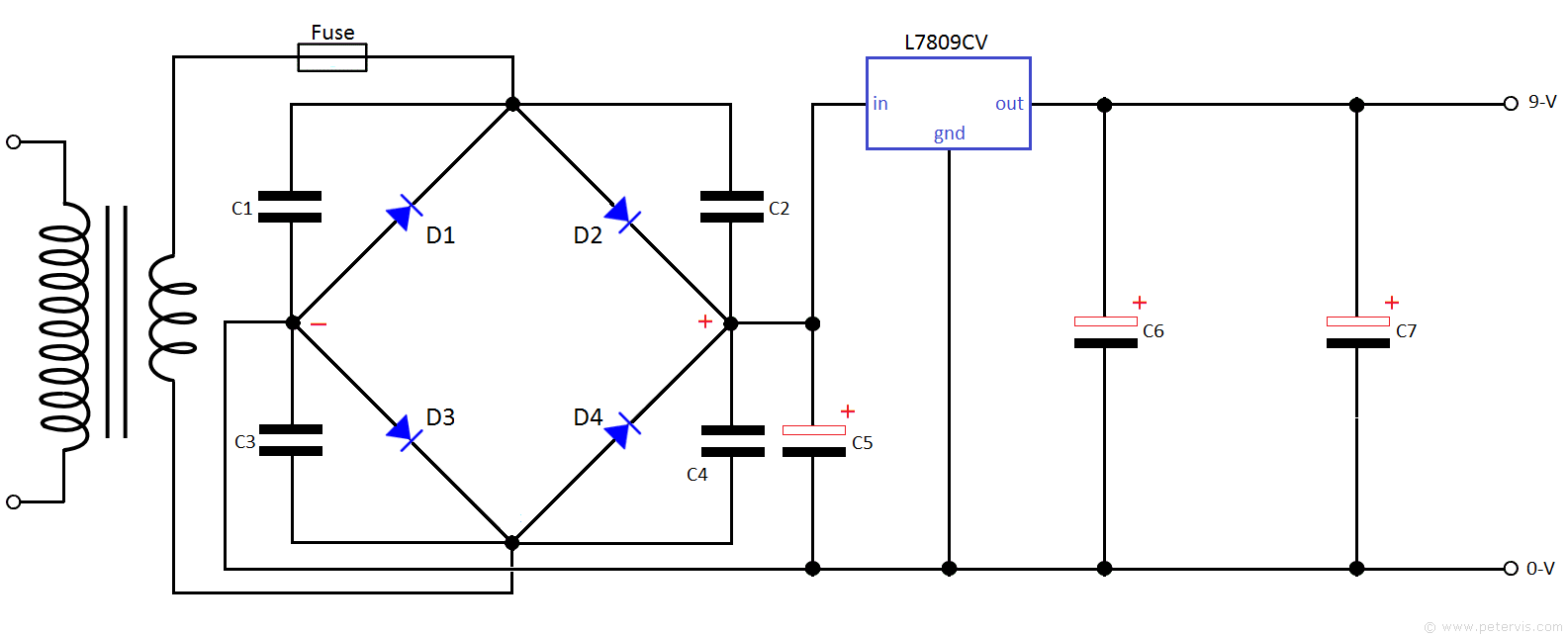
This 9 V power supply board uses a voltage regulator (L7809CV) to establish a precise and regulated 9 V rail. For the discrete MOSFET quadraphonic circuits, we need the voltage to be precise and very smooth. Consequently, I use 0.1 µF metallised polyester film capacitors in the bridge rectifier part of the circuit consisting of 1N4004 rectifier diodes. Providing the voltage regulators are good quality and genuine, there should be no hum introduced to the quadraphonic circuits. This type of circuit has worked well for me in the past and is also used in high-end commercial applications.
Board Layout


Component List
| Part Number | Value | Additional |
| D1 | 1N4004 | Power Diode |
| D2 | 1N4004 | Power Diode |
| D3 | 1N4004 | Power Diode |
| D4 | 1N4004 | Power Diode |
| C1 | 0.1 µF | 10 %, 630 V, (Metallised Polyester) |
| C2 | 0.1 µF | 10 %, 630 V, (Metallised Polyester) |
| C3 | 0.1 µF | 10 %, 630 V, (Metallised Polyester) |
| C4 | 0.1 µF | 10 %, 630 V, (Metallised Polyester) |
| C5 | 4700 µF | 16 V Electrolytic |
| C6 | 4700 µF | 25 V Electrolytic |
| C7 | 4700 µF | 25 V Electrolytic |
| Voltage Regulator | L7809CV | +9 V Regulator |
| Mains Transformer | 9 V to 12 V AC at 1 A | Minature type |
| Stripboard | 24-strips × 56-holes |
On eBay, I managed to get a bag of 100 rectifier diodes for around a pound and they seem to work well in the bridge rectifier part of the circuit. I managed to get ten metallised polyester film capacitors for around a pound, and these are the 630 V ones with lead spacing of 7-holes, which fit into the layout without the need for any bending. The electrolytic capacitors were recycled and ideally they should be greater than 1000 µF. Capacitor C5 should have voltage rating that is greater than the dc output voltage of the bridge rectifier. Capacitors C6 and C7 (after the 9 V regulator) should be 16 V or more. With voltage regulators, be aware as there are many fakes out there; hence measure the output voltage to be sure. For mounting the components, I managed to get a pack of five strip-boards for less than three pounds. They are a little too thin for my liking but adequate for the build and my poverty-stricken budget.
This Article Continues...
Quadraphonic Decoder Using MOSFET TransistorsBuild Your Own Matrix Decoder Circuit -- WW Article
Circuit Diagram
Cuts and Links
2N7000 Transistor Layout
Decoder Board Layouts
Board Preparations
Completed Front Channel Board
Completed Back Channel Board
Mixer Board Circuit
Completed Mixer Board
9V Power Supply Circuit
9V Power Supply Completed Build
Quadraphonic SQ Decoder Testing
