Marking Out the Baseboard and Installing the Screws
Building The Little Whippersnapper's Crystal Radio will introduce your whippersnapper to some excellent and useful skills for life's little challenges. Learning how to measure, marking with a pencil on timber, learning how to cut timber and softwoods, drilling, and using a slotted screwdriver, are all very important life skills.
When I was a little whippersnapper, I loved the woodworking class, because it was the most enjoyable time in school. There is a link to my woodwork school report in the Tupper's Self-Referential Formula article. Hey, there is nothing wrong working with your hands building things, because a chair and a table will help someone to sit down and eat. It is a nice age-old profession from the biblical era.
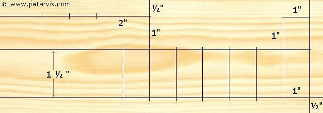
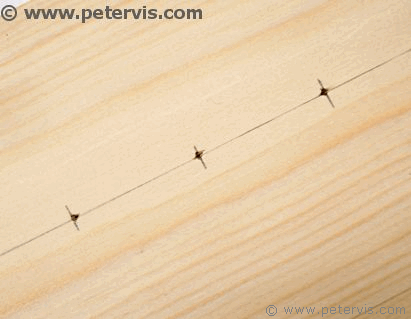
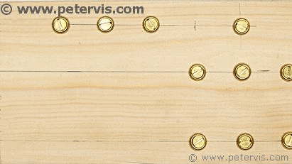
It is so simple. There is a half-inch border on the right hand side, indicated by the pencil lines. There will be two rows of screws. The rows are 1 ½ inch apart. The screws on each row will be 1-inch apart.
As Sir Alan Sugar would say, "It don't get no easier than that!"
Here is the plan view. As you can see, there is also a 1-inch square marking above the rows. The four screws that will go there are for the LT700 audio transformer. The transformer is optional in this project, but if you install it then you could try out some simple one transistor amplifier circuits with your crystal radio. There are many circuits on the Internet to try out.
Pass the Gimlet Son...
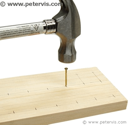
Chances are that you will not have a gimlet in your toolbox, or even know what it is. It is a small hand-drill, which creates a guide hole for a screw. Using a gimlet to make a small guide hole helps the screw threads to catch quickly. It is a precision tool because you can control precisely how deep to make the hole. It also prevents the wood from splitting.
In this project, you do not need the holes to come through the other end. You want them just deep enough for the screw threads to catch-on. If you do not have a gimlet, then you could use a very thin nail and tap it into the wood. It has to go in about 5 mm. Hopefully this will be enough for the screw threads to catch. Once the screw threads are in, it should be easy from that point forward. However, if you have the big bucks, a 1 mm diameter hand-drill is ideal, because they are very small drills for making precision guide holes. Of course, it goes without saying that only an adult should use this tool.
Ideally you need a drill to make these guide holes, however if you are using a nail, then they will have to be around 5 mm deep. If you are finding it difficult to install the screws, then make the holes bigger and deeper.
If you are working near a lake, then the moisture in the timber will make it difficult to install the screws and they will go just in, but not all the way. This is known as the just-in-timber-lake problem! :-)
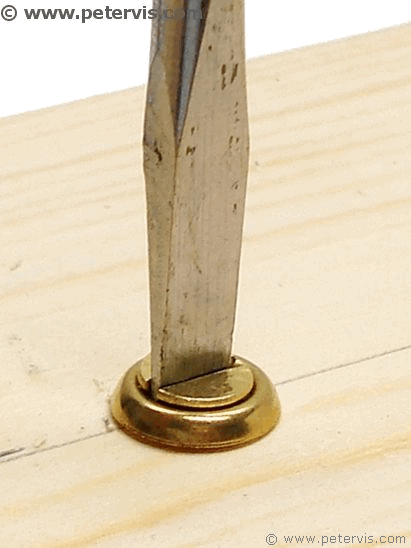
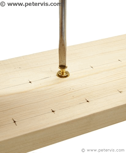
As you can see, a nice slotted screwdriver does the job perfectly.

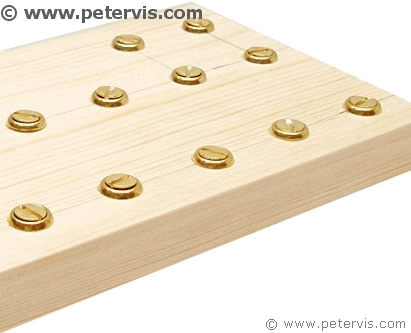
Here is a part finished board. I still need to install the screw cups for the ferrite rod antenna coils.
For the ferrite coil terminals, you need to make a half-inch border from the top. Notice how one screw aligns with the second column of screws installed earlier. The second terminal screw is 2-inches away, and the other two 1-inches apart.
Hey, move over NASA. The Little Whippersnapper's Crystal Radio is coming, and it is going to detect all the radio signals, your million dollar radios cannot detect!
This Article Continues...
Making a Crystal Radio Electronics LabMaking a Crystal Radio - The Little Whippersnapper's Parts List
Crystal Radio Baseboard 4-inch by 12-inch by 1/2-inch
No. 6 Brass Screw Cups & No. 6 Screws 1/2-inch
Marking Out the Baseboard and Installing the Screws
Making the coil
Crystal Radio Coil
Crystal Radio Coil Winding
Crystal Radio Coil Terminals
Connecting the Crystal Radio Coil
Main parts
Crystal Radio Diode
Germanium Diode Test
Crystal Radio Earphone
Crystal Radio Circuit
Crystal Radio Specification
Optional
Potentiometer Mounting Bracket
RFC - Radio Frequency Choke
Project Power Supply Wiring
10k Potentiometer Wiring
BC549C Lead Extensions for Future Amplifier Projects
Wiring the Speaker to the LT700 Transformer
Credits
The Little Whippersnapper's Radio