Project Power Supply Wiring
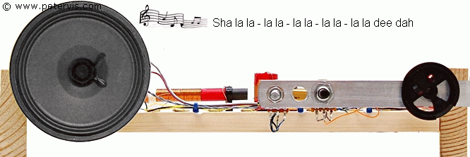
Building a crystal radio, always leads to building a single transistor common emitter amplifier stage. This is just one of those things that all beginners try out, and it is of course a futile experiment, but we can learn so much more from our mistakes and failures.
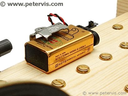
I decided to add a power supply facility so that the whippersnappers could build simple transistor circuits for experimentation. I found this clip at my local car spares shop. I do not know what it is for but for 20p it is ideal to hold the battery!
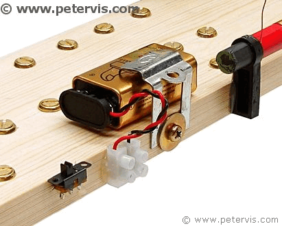
A power switch is very useful because removing the battery clips every time will make them loose, hence a recycled slide switch is probably the best thing. I stuck it there with some hot glue and it is fixed for life! I just love the hot glue gun I bought, because it solves so many problems!
I decided to add a screw terminal so that if in the future they wanted to power their experimental circuits from a DC adapter, then they had the option there. Screw terminals are very low cost, and I bought these from my local electrical store. But of course you should always use what you have at hand, or what is available cheap, because the all of these little things add to the total cost, and ideally you want to keep the runaway cost to a minimum.
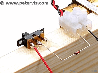
Just in case the whippersnappers decide to connect the power supply the wrong way round, I have included this protection diode. It is just a common garden variety 1N4148, and it will protect the transistors from reverse voltage. The protection diode is optional, and if you do not have one then just connect a wire loop instead.
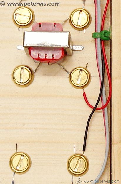
This is where the red and black wires connect, and as you can see, it is very simple. From here, they can tap the voltage rails for any project they may be working on.
This Article Continues...
Making a Crystal Radio Electronics LabMaking a Crystal Radio - The Little Whippersnapper's Parts List
Crystal Radio Baseboard 4-inch by 12-inch by 1/2-inch
No. 6 Brass Screw Cups & No. 6 Screws 1/2-inch
Marking Out the Baseboard and Installing the Screws
Making the coil
Crystal Radio Coil
Crystal Radio Coil Winding
Crystal Radio Coil Terminals
Connecting the Crystal Radio Coil
Main parts
Crystal Radio Diode
Germanium Diode Test
Crystal Radio Earphone
Crystal Radio Circuit
Crystal Radio Specification
Optional
Potentiometer Mounting Bracket
RFC - Radio Frequency Choke
Project Power Supply Wiring
10k Potentiometer Wiring
BC549C Lead Extensions for Future Amplifier Projects
Wiring the Speaker to the LT700 Transformer
Credits
The Little Whippersnapper's Radio