Potentiometer Mounting Bracket
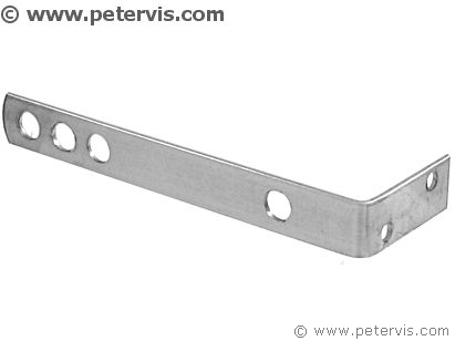
A bracket for mounting electronic potentiometers onto a chassis is expensive; however, an angled bracket used in the building trade is much cheaper and does the same job! It can have three to four holes that are large enough for the potentiometers and the tuning capacitor. This is an almost perfect solution for less than 60p! Moreover, it does not involve drilling!
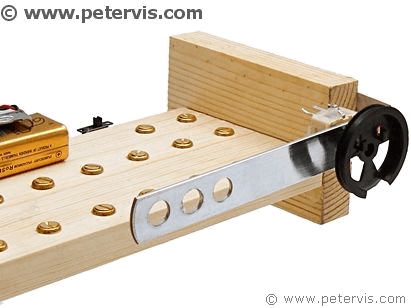
These modern variable tuning capacitors have two tiny screw holes at the front for mounting; however, I decided not to make any because this is toughened steel and it would be a nightmare to drill. Instead, I used two blobs of hot melt glue from the glue gun, and it was secured for all time!
I decided to fit the angled metal bracket this way because it keeps the potentiometers out of the way, and it leaves a lot of space on the board for the circuit.
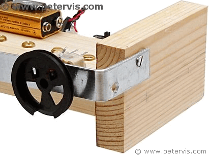
The orientation of the variable capacitor is such that you could install a dial with the string mechanism. I do not think many people will know how they work though...
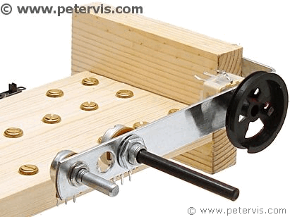
The two potentiometers secured wonderfully as well with their nut and washer assembly. It looks like a professional job now! Hey, I am a professional...
Although the advice in the Ladybird book radio is to cut the potentiometer shaft, I would not be too hasty about that until I have found a box and a knob for it. This is because sometimes when you cut the shaft, and then install the radio into the box; you find that it is slightly short! This is because the plastic knob requires a little extra length, which you had not made an allowance for... Therefore, I would leave that to the very end until the box, and the knobs are found.
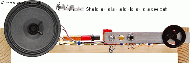
The metal bracket and the speaker are on the same level plane, so if they find a box for it, then the chassis will simply slide into it. The box will simply need some holes at the front for the speaker and the controls.
This Article Continues...
Making a Crystal Radio Electronics LabMaking a Crystal Radio - The Little Whippersnapper's Parts List
Crystal Radio Baseboard 4-inch by 12-inch by 1/2-inch
No. 6 Brass Screw Cups & No. 6 Screws 1/2-inch
Marking Out the Baseboard and Installing the Screws
Making the coil
Crystal Radio Coil
Crystal Radio Coil Winding
Crystal Radio Coil Terminals
Connecting the Crystal Radio Coil
Main parts
Crystal Radio Diode
Germanium Diode Test
Crystal Radio Earphone
Crystal Radio Circuit
Crystal Radio Specification
Optional
Potentiometer Mounting Bracket
RFC - Radio Frequency Choke
Project Power Supply Wiring
10k Potentiometer Wiring
BC549C Lead Extensions for Future Amplifier Projects
Wiring the Speaker to the LT700 Transformer
Credits
The Little Whippersnapper's Radio
